When your app sends an HTTP request, a lot happens before the server sees it. The request gets encrypted, split into pieces, addressed, turned into electrical or radio signals, forwarded through several machines, and put back together on the other end. Your code doesn’t deal with any of it. It calls fetch() and waits for a response.
That separation comes from layering, and the OSI model is the standard way to describe it. OSI stands for Open Systems Interconnection. ISO published it in 1984 as a seven-layer reference model.
The internet doesn’t actually run on OSI. It runs on TCP/IP, which is older and has fewer layers. But the OSI terms stuck, so when people talk about a “layer 4 load balancer” or “a layer 2 issue”, they mean OSI layers.
In this post I’ll go through each layer, then follow one request from a client to a server and see what each layer adds.
Why we need a model
Without a shared model, a few things get hard.
- Apps would need to know the network medium. You’d write one version of your HTTP client for Ethernet, another for Wi-Fi, another for LTE and another for fiber.
- Upgrading network equipment would be risky. If a router had to understand application protocols, replacing it could break apps it has nothing to do with.
- Every change would ripple. With layers, each part can change independently. Wi-Fi has gone through several generations without HTTP changing. HTTP went from 1.1 to 2 to 3 without anyone replacing their switches.
Each layer offers a service to the layer above and relies on the layer below. As long as that contract holds, the internals of a layer can change.
The seven layers
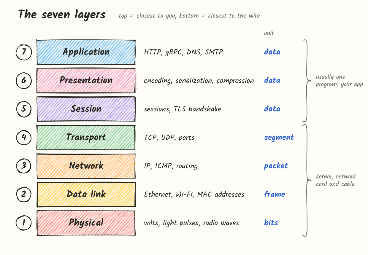
| Layer | Name | Responsible for | Examples |
|---|---|---|---|
| 7 | Application | The protocol the app speaks | HTTP, gRPC, DNS, SMTP, FTP |
| 6 | Presentation | How data is represented | UTF-8, JSON, Protobuf, compression |
| 5 | Session | Setting up and maintaining a conversation | TLS handshake, session resumption |
| 4 | Transport | Delivering data to the right process | TCP, UDP |
| 3 | Network | Delivering packets between hosts, across networks | IP, ICMP |
| 2 | Data link | Delivering frames to the next device on a link | Ethernet, Wi-Fi |
| 1 | Physical | Sending bits as signals | copper, fiber, radio |
A common mnemonic, from 7 down to 1, is “All People Seem To Need Data Processing”.
Each layer also has a name for its unit of data, called a PDU (protocol data unit):
- Layers 7, 6 and 5: data
- Layer 4: segment (datagram for UDP)
- Layer 3: packet
- Layer 2: frame
- Layer 1: bits
These names come in handy. If someone mentions dropped frames, you look at the link. Dropped packets point to routing.
OSI vs TCP/IP
One thing to know before going further: TCP/IP has four layers, and it folds OSI’s top three into one.
| TCP/IP layer | OSI layers | Where it runs |
|---|---|---|
| Application | 7, 6, 5 | your program and its libraries |
| Transport | 4 | OS kernel |
| Internet | 3 | OS kernel |
| Link | 2, 1 | network card, driver, cable |
So in real systems, there’s no separate presentation or session software. JSON encoding, gzip and TLS usually all happen inside your process, often in one HTTP library. That’s why layers 1 to 4 are well defined, while people still argue about what belongs in 5 and 6.
Layer 7: Application
This is the layer your code works with directly. Application protocols define what a conversation looks like:
- HTTP has methods, paths, headers, a body and status codes.
- DNS has queries with a name and a record type.
- SMTP sends mail with commands like
MAIL FROM,RCPT TOandDATA. - gRPC calls a method on a service.
These protocols don’t care how the bytes travel, whether that’s fiber, Wi-Fi or a cable across a desk.
Note that the layer is the protocol, not the program. Chrome isn’t a layer 7 thing; HTTP is the layer 7 protocol Chrome uses.
Layer 6: Presentation
Two machines can both speak HTTP and still get confused if they represent data differently. The presentation layer deals with that. Its usual jobs are:
- Translation / serialization. Converting in-memory data into a format you can send, and back. JSON, Protocol Buffers, MessagePack, XML and ASN.1 are examples. Calling
json.loads()on a server is presentation layer work. - Character encoding.
"Hello"in ASCII or UTF-8 is the bytes48 65 6c 6c 6f. In EBCDIC, which IBM mainframes use, it’s different bytes entirely. - Compression. Making data smaller before sending it and expanding it after, with gzip, Brotli or zstd.
- Encryption and decryption.
In practice these don’t sit neatly in layer 6. HTTP handles compression itself through the Content-Encoding header, which is layer 7. TLS is placed at layer 6 in some books, layer 5 in others, and sometimes at “4.5”. TLS was built for TCP/IP, not for OSI, so it doesn’t map cleanly. I think of it this way: the TLS handshake sets up a session (layer 5), and encrypting the data is a transformation (layer 6).
Email attachments are a good example. You attach a photo that’s already compressed as JPEG. Since email was originally designed for text, the client encodes the attachment as Base64. The receiving client decodes the Base64 and then decodes the JPEG. The image itself never changed, only how it was represented in transit.
Layer 5: Session
The session layer handles opening, maintaining and closing a conversation between two machines.
The original OSI design included things like dialog control (whose turn it is to send) and checkpoints, so a long transfer that failed partway could resume instead of starting over. NetBIOS and RPC are the usual textbook examples.
Today, those responsibilities are spread across other protocols:
- The TLS handshake sets up a secure session, and TLS session resumption lets a client reconnect without a full handshake.
- HTTP/2 and HTTP/3 run many request streams over a single connection.
- Cookies and session tokens link separate HTTP requests to one logged-in user, although that’s application logic.
In practice you won’t find a component that is “the session layer”. Its work is done by TLS, HTTP and your application.
Layer 4: Transport
Layer 3 delivers a packet to a machine. That machine is running lots of processes, and layer 4 gets the data to the right one. Depending on the protocol, it can also make delivery reliable.
| Function | Description |
|---|---|
| Port addressing | Port numbers identify which process gets the data |
| Segmentation and reassembly | Breaking a byte stream into segments and rebuilding it in order |
| Reliability | Detecting lost data and resending it |
| Error checking | Checksum on each segment |
| Flow control | Not sending faster than the receiver can handle |
| Congestion control | Not sending faster than the network can handle |
A server listens on a known port, like 443 for HTTPS or 5432 for PostgreSQL. The client uses a temporary (ephemeral) port such as 54321. A connection is identified by source IP, source port, destination IP, destination port and protocol. Because each connection gets a different source port, one laptop can have many connections open to the same server.
TCP and UDP take very different approaches:
| TCP | UDP | |
|---|---|---|
| Connection | Three-way handshake (SYN, SYN-ACK, ACK) | No handshake |
| Delivery | Reliable, resends lost data | Best effort |
| Ordering | Guaranteed | Not guaranteed |
| Unit | Segment, part of a byte stream | Datagram, a standalone message |
| Header size | 20 to 60 bytes | 8 bytes |
| Common uses | HTTP/1.1, HTTP/2, SSH, databases | DNS, video calls, games, QUIC (HTTP/3) |
With TCP, the app gets an ordered stream of bytes. Say you write 10 MB to a socket. TCP splits it into segments, gives every byte a sequence number, waits for acknowledgements and resends anything that goes missing. The other side reads the same 10 MB in the same order.
UDP turns each sendto() call into one datagram. It either arrives whole or it doesn’t, and handling order is up to your application. That fits real-time traffic well, since a late video frame is useless and retransmitting it just adds delay. QUIC, which HTTP/3 uses, runs on UDP and implements its own reliability in user space, so it doesn’t depend on OS TCP stacks being updated.
Something a lot of explanations get wrong: UDP doesn’t segment data. Only TCP does. A UDP datagram goes out as a single unit, and if it’s too big for the network, the network layer has to handle it.
TCP segment size is based on the MSS (maximum segment size), which in turn comes from a limit at layer 3. More on that below.
Layer 3: Network
The network layer moves packets from one host to another across different networks, through routers that know nothing about either endpoint.
| Function | Description |
|---|---|
| Logical addressing | IP addresses indicate where a host is on the network |
| Routing | Choosing the path packets take |
| Forwarding | Sending each packet to the next hop |
| Fragmentation | Splitting packets that are too big for a link |
A MAC address (layer 2) is tied to a network card. It identifies the device but says nothing about where it is. An IP address depends on which network you’re connected to, much like a postal address. Since IP addresses are hierarchical, routers don’t need to know about every host. They only need to know where each address range should go.
For each packet, a router finds the most specific match for the destination IP in its routing table and forwards the packet out that interface. It also decrements the TTL (time to live) field and drops the packet when TTL reaches zero, so a routing loop can’t keep a packet alive forever. traceroute relies on this: it sends packets with TTL 1, 2, 3 and so on, and each router that drops one replies with an ICMP message that reveals its address.
An IP packet header includes:
- source IP address
- destination IP address
- TTL (called hop limit in IPv6)
- protocol of the payload (6 = TCP, 17 = UDP)
- total length, plus the identification and offset fields used for fragmentation
Protocols at this layer:
| Protocol | Purpose |
|---|---|
| IP (v4 and v6) | Addressing and routing |
| ICMP | Errors and diagnostics, used by ping and traceroute |
| IPsec | Encrypting and authenticating IP packets, common in VPNs |
| ARP | Looking up the MAC address for an IP on the local network |
ARP is a bit of an odd one. It connects layers 3 and 2, and it travels directly inside Ethernet frames rather than inside IP packets. Depending on the source, it’s called layer 2, layer 3 or “2.5”. What it does is simple enough: “who has 192.168.1.1? tell 192.168.1.20“.
MTU
The Maximum Transmission Unit is the largest packet a link can carry in one piece, in bytes. On Ethernet it’s usually 1500 bytes.
The limit comes from layer 2, since it’s really the maximum size of a frame’s payload. But it matters most at layer 3, because the IP packet is what has to fit.
| Term | Meaning |
|---|---|
| MTU | Largest IP packet a link can carry. 1500 on standard Ethernet. |
| MSS | Largest TCP payload per segment: MTU minus IP and TCP headers. For IPv4, 1500 - 20 - 20 = 1460. |
| Path MTU | The smallest MTU along the whole route, which is the actual limit end to end. |
| Jumbo frames | Ethernet with an MTU of around 9000, mostly used inside data centers. |
During the handshake, each TCP side advertises its MSS so that segments already fit and don’t need to be split later. This is the main reason normal web traffic rarely gets fragmented.
What happens with a packet bigger than the MTU:
- The packet gets fragmented (IPv4, if allowed).
- Or the packet gets dropped.
- Often the sender gets an error message like “Packet Too Big”.
Why MTU matters:
| Reason | Explanation |
|---|---|
| Performance | Larger MTU means less fragmentation and less header overhead |
| Latency | Small MTU means more fragments and more reassembly work |
| Packet loss | An MTU mismatch can cause packets to be dropped |
| Security | Fragmentation has a history of being used in attacks |
Fragmentation
If a packet is bigger than the next link’s MTU and its Don’t Fragment (DF) bit isn’t set, an IPv4 router splits it into fragments. Every fragment is a full IP packet with its own header, and they all share the same identification value so the receiver can reassemble them.
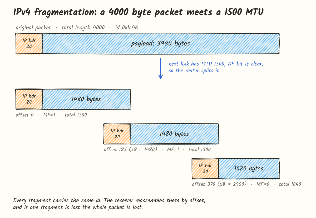
The numbers:
- The original packet is 4000 bytes: a 20 byte header and 3980 bytes of payload.
- Each fragment needs its own 20 byte header, so a 1500 byte fragment holds 1480 bytes of payload.
- The offset field counts in 8 byte units, so every fragment payload except the last must be a multiple of 8. 1480 / 8 = 185.
- Fragment 1: offset 0, 1480 bytes, More Fragments (MF) = 1
- Fragment 2: offset 185, 1480 bytes, MF = 1
- Fragment 3: offset 370, 1020 bytes, MF = 0 (last one), total length 1040
1480 + 1480 + 1020 = 3980, so all the data is there.
The downside is that losing any one fragment means the whole packet can’t be reassembled, so the other fragments are thrown away too. Firewalls have trouble with fragments because only the first one includes the TCP/UDP header with the ports. There have also been attacks that use overlapping fragment offsets.
If DF is set, the router drops the packet and sends an ICMP “Fragmentation Needed” message back with the smaller MTU. The sender then uses smaller packets. That’s Path MTU Discovery, and modern operating systems set DF by default so it works.
IPv6 routers never fragment. Only the sender is allowed to, and routers that get a packet that’s too large drop it and reply with ICMPv6 “Packet Too Big”.
This leads to a common real-world problem. Path MTU Discovery only works if the ICMP messages reach the sender. When a firewall blocks all ICMP, large packets just disappear. Connections open normally and small requests work, but anything with a large response hangs. This is known as an MTU black hole. It shows up a lot with VPNs and tunnels, because they reduce the effective MTU. The usual fix is MSS clamping, where a router rewrites the MSS in the TCP handshake to a value that fits.
You can check the path MTU with ping by setting DF and a payload size. 1472 bytes of data plus an 8 byte ICMP header plus a 20 byte IP header adds up to 1500:
# Linux
ping -M do -s 1472 example.com

# macOS
ping -D -s 1472 example.com
If you get “message too long” or “frag needed”, reduce the size until the ping goes through.
Segmentation vs fragmentation
These two are easy to confuse:
| Segmentation | Fragmentation | |
|---|---|---|
| Layer | Transport (4) | Network (3) |
| Done by | TCP | IP (routers in IPv4, only the sender in IPv6) |
| What’s split | The application’s byte stream | An IP packet |
| Why | Data is bigger than one segment (MSS) | Packet is bigger than a link’s MTU |
| When | Planned ahead using the MSS | On the fly, when a packet hits a smaller link |
| Unit | Segment | Fragment |
| Reassembly | TCP, by sequence number | IP, by identification and offset |
| If one piece is lost | Only that segment is resent | The whole packet is lost |
Segmentation is normal and happens on almost every TCP connection. Fragmentation is a fallback that you generally want to avoid.
Layer 2: Data link
Layer 3 decides where a packet should go next. Layer 2 delivers it over a single link, such as laptop to Wi-Fi access point, switch to router, or router to router. It doesn’t look beyond the next hop.
| Function | Description |
|---|---|
| Framing | Adding a header and trailer so the receiver knows where the frame begins and ends |
| Physical addressing | Using MAC addresses to identify devices on the link |
| Error detection | Checksum on each frame to catch corrupted bits |
| Media access control | Deciding who can transmit on a shared medium |
| Flow control | Asking a sender to pause when the receiver can’t keep up |
A MAC address is 48 bits, like a4:83:e7:12:9c:01, and belongs to a network interface. The first half traditionally identifies the manufacturer.
Frame structure
A frame is a packet with a link-layer header in front and a trailer at the end. This is a standard Ethernet frame with a small TCP payload:
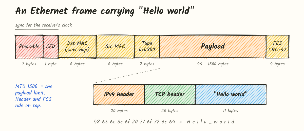
| Field | Size | Purpose |
|---|---|---|
| Preamble | 7 bytes | Alternating 1s and 0s that help the receiver sync its clock |
| SFD | 1 byte | Start frame delimiter, marks where the frame begins |
| Destination MAC | 6 bytes | Receiver on this link |
| Source MAC | 6 bytes | Sender |
| Type | 2 bytes | Payload type: 0x0800 IPv4, 0x86DD IPv6, 0x0806 ARP |
| Payload | 46 to 1500 bytes | The IP packet |
| FCS | 4 bytes | CRC-32 checksum |
The network card handles the preamble and SFD, and they’re usually counted as part of the physical layer. Wireshark doesn’t show them. Captures start at the destination MAC.
Let’s put "Hello world" into a frame. The 11 characters are the bytes 48 65 6c 6c 6f 20 77 6f 72 6c 64. TCP adds a 20 byte header and IP adds another 20, so the packet is 51 bytes. Ethernet then adds a 14 byte header and a 4 byte FCS, for a 69 byte frame, plus the 8 bytes of preamble and SFD.
The 46 byte minimum payload matters for small packets. Over UDP, the same message makes a 39 byte packet (20 + 8 + 11), so Ethernet pads it with 7 zero bytes. This keeps frames at least 64 bytes long, a leftover from shared coax cables, where a frame had to be long enough for collisions to be detected while it was still being transmitted.
Error detection
You’ll often read that layer 2 does error detection and correction. For Ethernet, it’s only detection. The receiver computes the CRC, and if it doesn’t match the FCS, the frame gets dropped without notice. There’s no repair and no retransmission at this layer. TCP at layer 4 sees the gap and resends the data.
Wi-Fi works differently because radio links lose a lot more data. The receiver acknowledges each unicast frame, and the sender resends at layer 2 if no ACK arrives. That’s part of the reason Wi-Fi speeds drop so much with a weak signal: much of the airtime goes to retries.
Switches and ARP
A switch operates at layer 2. It learns which MAC addresses are on which port by looking at the source MAC of incoming frames. When a frame comes in, it checks the destination MAC and sends the frame out the matching port. If it hasn’t seen that MAC yet, it sends the frame out every port and learns the location from the reply.
So which destination MAC does your laptop use when sending a packet to 203.0.113.7, a server on another network?
It’s not the server’s MAC. The laptop’s routing table shows the server isn’t local, so the frame goes to the default gateway, which is your router. The laptop uses ARP to find the router’s MAC, then sends a frame addressed to the router’s MAC with a packet inside addressed to the server’s IP. This comes up again later when we look at routers.
Layer 1: Physical
Layer 1 has no addresses or headers. It only deals with bits, sent as voltage on copper, light in fiber, or radio waves.
| Medium | Signal | Examples |
|---|---|---|
| Copper twisted pair | Electrical | Cat5e, Cat6 Ethernet cables |
| Optical fiber | Light | Data center links, ISP backbones, FTTH |
| Wireless | Radio | Wi-Fi, Bluetooth, LTE, 5G |
It also covers the physical details: connectors (RJ45, LC), cable categories, pinouts, voltage levels, wavelengths, frequencies and bit rates. An unplugged cable, a link light that’s off, or 2.4 GHz Wi-Fi interference from a microwave are all layer 1 problems.
From frame to signal
The frame is first turned into a stream of bits. In ASCII, "Hello world" starts like this:
H        e        l        l        o
01001000 01100101 01101100 01101100 01101111
The network card then turns those bits into a signal. The method it uses is called line coding.
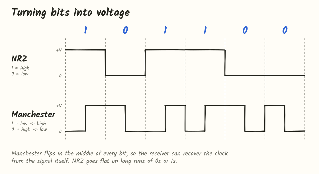
NRZ (Non-Return-to-Zero): 1 is high voltage and 0 is low voltage. This is simple, but it breaks down on long runs of the same bit. A thousand 0s is a flat line, and the receiver can’t tell 999 zeros from 1001. Its clock drifts out of sync with the sender’s and bits get miscounted.
Manchester encoding: every bit has a transition in the middle. Ethernet’s convention is that 1 goes low to high and 0 goes high to low. Since the signal changes on every bit, the receiver can recover the clock from the data. The trade-off is roughly twice the bandwidth of NRZ.
10 Mbps Ethernet (10BASE-T) used Manchester encoding. Faster Ethernet uses more efficient schemes:
- 100BASE-TX: 4B5B with MLT-3 (three voltage levels)
- 1000BASE-T: PAM-5 (five levels) on all four wire pairs at the same time
- 10GBASE-T: PAM-16
All of them aim to carry more bits per symbol while still giving the receiver enough transitions to stay in sync.
On the receiving end, the network card samples the signal, recovers the clock, turns it back into bits, finds the SFD and passes the frame up to layer 2. From there each layer does the reverse of what the sender did.
Encapsulation
When sending, each layer takes what it got from the layer above, treats it as payload, and adds its own header. This is called encapsulation.
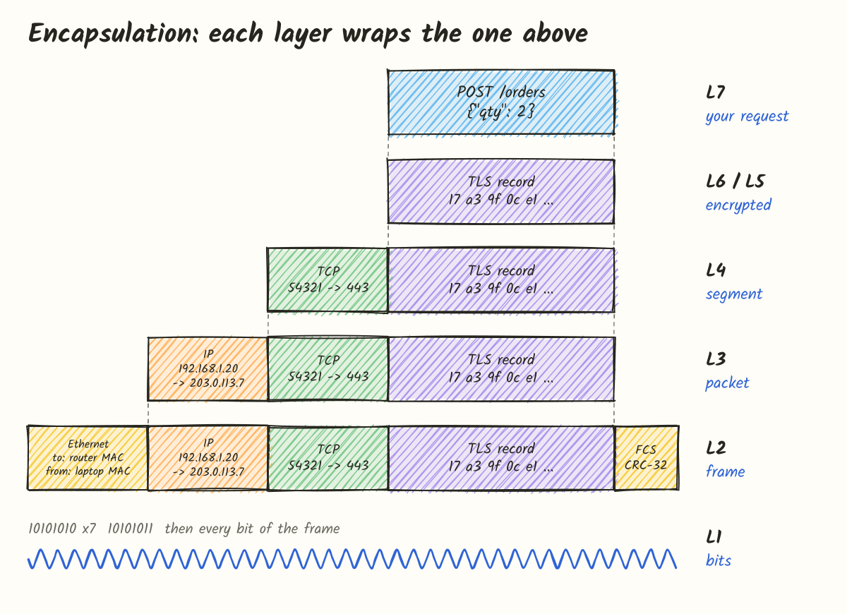
Layers don’t inspect their payload. TCP doesn’t know it’s carrying a TLS record, and IP doesn’t know it’s carrying TCP. Ethernet only has the 2 byte type field, which tells the receiver which layer 3 protocol to hand the payload to. This is what allows a layer to be replaced without affecting the others.
On the receiving side, each layer reads and removes its own header, uses it to decide where the payload goes, and passes it up. That’s decapsulation.
Following an HTTPS POST
Here’s a concrete example: a client at 192.168.1.20 sends POST /orders with the body {"qty": 2} to a server at 203.0.113.7.
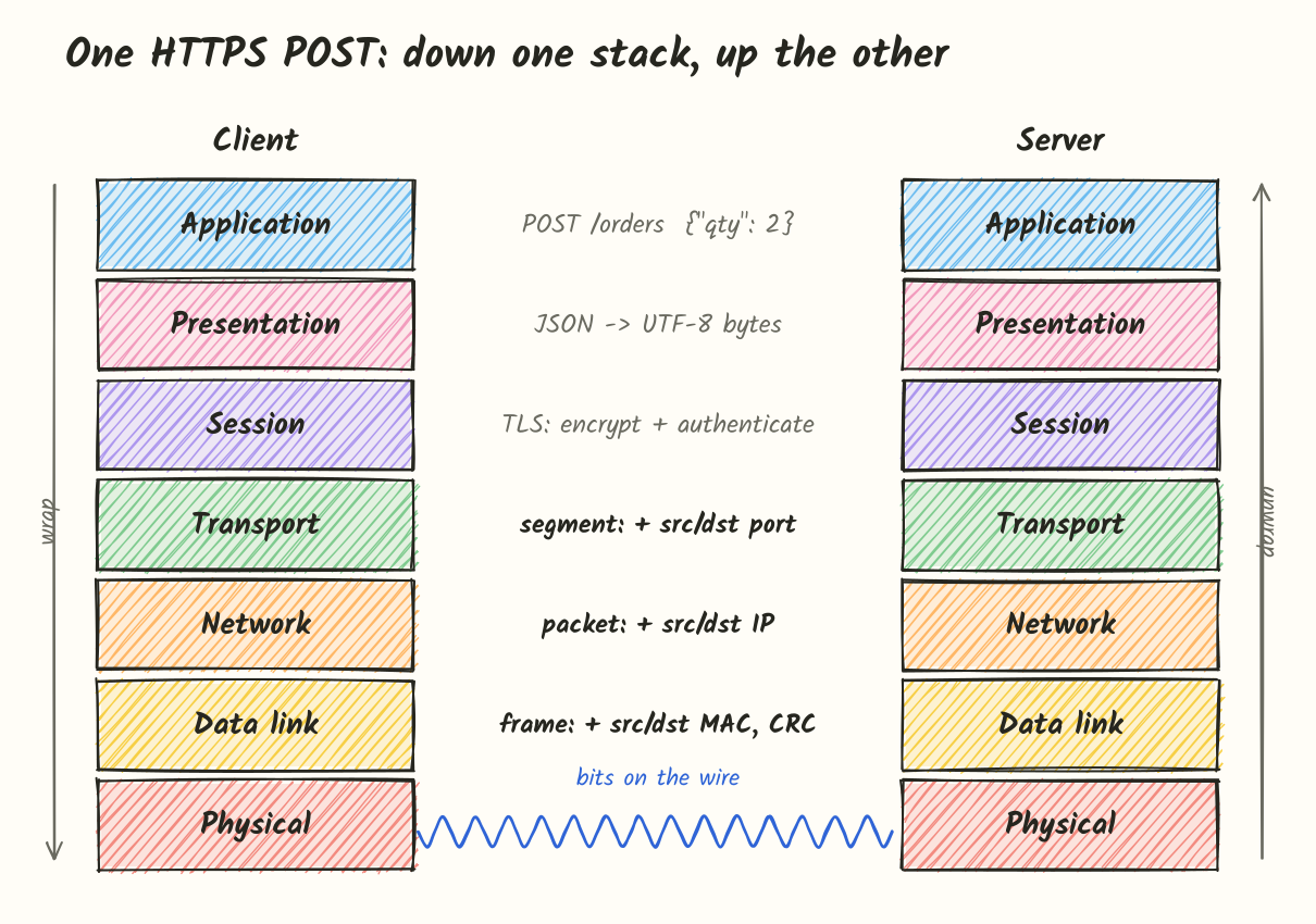
On the client, from top to bottom:
- Application: the HTTP library builds the request with method, path,
HostandContent-Typeheaders, and the JSON body. - Presentation: the body is serialized to JSON and encoded as UTF-8.
- Session: TLS has already done its handshake, so both sides have session keys. The HTTP bytes are encrypted into TLS records, and from this point on the request is unreadable without the keys.
- Transport: the kernel’s TCP stack splits the encrypted data into segments of up to 1460 bytes of payload each, and adds headers with source port
54321, destination port443and sequence numbers. - Network: IP adds source address
192.168.1.20, destination203.0.113.7, TTL 64 and protocol 6 (TCP). - Data link: the server isn’t on the local network, so the frame’s destination is the router’s MAC. The source is the laptop’s MAC, the type is
0x0800, and the CRC is added at the end. - Physical: the Wi-Fi radio sends the bits on a 5 GHz carrier.
On the server, everything happens in reverse. The network card turns the signal into a frame. Layer 2 checks the CRC and confirms the destination MAC is its own. Layer 3 confirms the destination IP and sees protocol 6. Layer 4 finds the socket listening on port 443 and puts the segments back in order. TLS decrypts the data, the JSON gets parsed, and the handler runs.
With tcpdump you can see layers 2 to 4 of this. The -e flag adds link-layer headers to the output:
sudo tcpdump -e -n -i en0 'tcp port 443'03:12:10.482113 a4:83:e7:12:9c:01 > 3c:22:fb:7a:10:5e, ethertype IPv4 (0x0800), length 78:
192.168.1.20.54321 > 203.0.113.7.443: Flags [S], seq 1829301, win 65535,
options [mss 1460,...], length 0Reading from left to right: MAC addresses and EtherType (layer 2), IP addresses (layer 3), then ports, TCP flags, sequence number and the MSS of 1460 (layer 4). Nothing appears from layers 5 to 7 because a SYN has no payload, and once data starts flowing you’d only see encrypted TLS records anyway.
Across networks
In reality, the client and server aren’t connected directly. There are switches and routers in between, and each one only goes as far up the stack as it needs to.
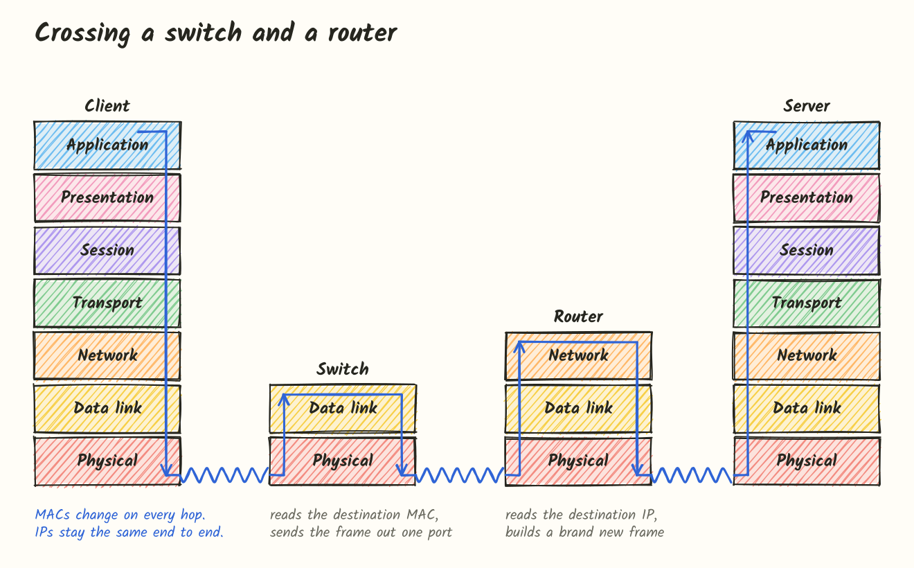
A switch goes up to layer 2. It checks the destination MAC and forwards the frame out one port. It never looks at the IP header.
A router goes up to layer 3. It removes the incoming frame, reads the destination IP, decrements the TTL, picks an outgoing interface, and creates a new frame with its own MAC as the source and the next hop’s MAC as the destination. Then it sends that frame out.
So as a packet travels:
- MAC addresses change at every hop, because they only apply to the current link.
- IP addresses stay the same from start to finish.
The big exception is NAT. Your home router changes the source IP from 192.168.1.20 to its public IP, and usually changes the source port as well. It keeps a table so it can translate the replies back. That means NAT, a layer 3 device, also modifies layer 4 data.
Middleboxes
The same idea explains the proxies, firewalls and load balancers you find in front of most production services. Calling one “layer 4” or “layer 7” describes how far up the stack it reads.
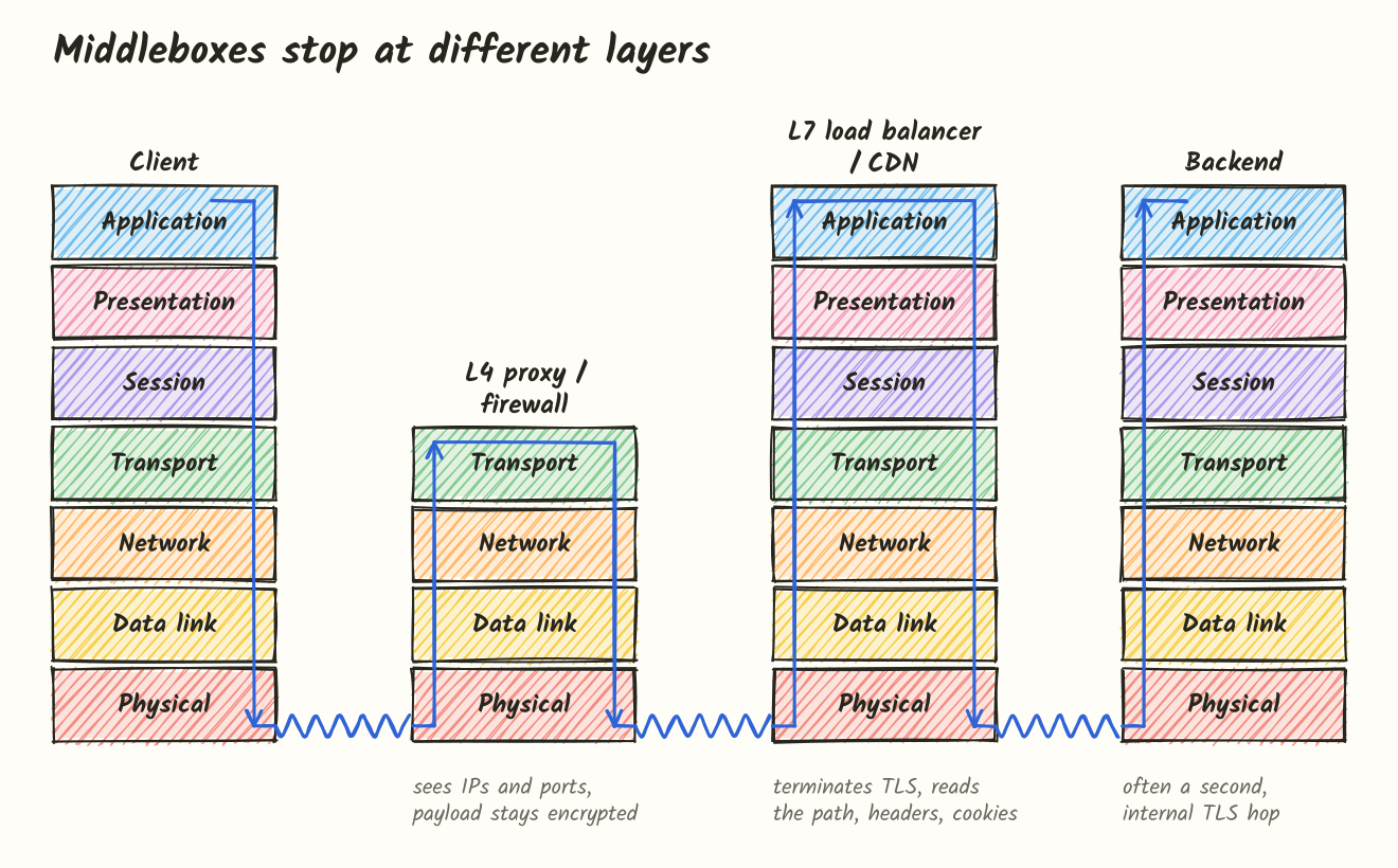
A layer 4 proxy, firewall or load balancer works with IPs and ports. It can allow or block traffic to 203.0.113.7:443 or spread TCP connections across backends, but it can’t read the encrypted traffic, so it doesn’t know which URL was requested. On the plus side, it doesn’t need your TLS certificate, adds very little latency, and works with any TCP or UDP protocol. Many L4 load balancers do read the SNI (server name) from the TLS ClientHello, which is sent unencrypted, to choose a backend.
A layer 7 load balancer, reverse proxy or CDN terminates TLS. It has your certificate and private key, decrypts traffic, and reads full HTTP requests. That lets it:
- route
/api/*and/images/*to different services - cache responses
- add or rewrite headers and URLs
- rate limit per user
- block malicious requests with a WAF
The costs are CPU for decryption, some added latency, and one more system that sees your traffic in plaintext. The load balancer also opens its own TCP connection to the backend, frequently with separate TLS. So the backend sees the load balancer’s IP as the source, unless the real client IP is passed in a header like X-Forwarded-For.
In short, layer 4 is fast and works with any protocol but can’t see much. Layer 7 can do a lot more, but it’s slower and needs your keys.
Debugging by layer
This is where the model is most useful day to day. Start at the bottom and work up.
| Layer | What to check | Tools |
|---|---|---|
| 1 Physical | Is the link up? | link lights, Wi-Fi signal, ethtool eth0 |
| 2 Data link | Can I reach devices on the local network? | arp -a, ip neigh |
| 3 Network | Can I reach the remote host, and what route does it take? | ping, traceroute, ip route |
| 4 Transport | Is the port open? | nc -vz host 443, ss -tlnp |
| 5/6 Session, presentation | Does the TLS handshake work? Is the certificate valid? | openssl s_client -connect host:443 -servername host |
| 7 Application | Is the request right, and what comes back? | curl -v, browser devtools |
| All | What’s actually being sent? | tcpdump, Wireshark |
If a tool succeeds at one layer, everything below that layer is working too. So if nc -vz api.example.com 443 connects, layers 1 to 4 are fine and you should look at TLS or HTTP. If ping fails but nc connects, something along the path is blocking ICMP. That’s a firewall setting, not a server problem.
Summary
- OSI has seven layers, and each one has a specific job: application, presentation, session, transport, network, data link and physical.
- Real networks use TCP/IP, which combines layers 5 to 7. That’s why those upper layers are less clearly defined in practice.
- On the way down, each layer wraps the data with its own header. On the way up, each layer removes it.
- Segmentation (TCP, layer 4) and fragmentation (IP, layer 3) are different things. TCP uses the MSS to avoid fragmentation.
- MAC addresses change at every hop, while IP addresses stay the same (except with NAT).
- Switches work at layer 2 and routers at layer 3. L4 load balancers see ports, and L7 load balancers see HTTP.
- To debug, start at layer 1 and move up.